LongRangeLocators Forums  

Go Back   LongRangeLocators Forums > Main Forums > All-Electronic LRLs

Reply
 
Thread Tools Display Modes
  #3176  
Old 03-15-2024, 03:35 PM
FrancoItaly FrancoItaly is offline
Guru
 
Join Date: Feb 2006
Location: Liguria, Italy
Posts: 1,350
Default

Quote:
Originally Posted by Rahman View Post
Hi Franco, my friend, should the selfie be horizontal or vertical, and the shield should be from inside the box
The shielding is not critical, the important thing is good electrical contact with the PCB ground and also the shielding of the handle.
Reply With Quote
  #3177  
Old 03-19-2024, 10:22 AM
FrancoItaly FrancoItaly is offline
Guru
 
Join Date: Feb 2006
Location: Liguria, Italy
Posts: 1,350
Default

I'm posting the material for building my lrl for a new forum member.
Attached Files
File Type: zip original lrl.zip (1.13 MB, 609 views)
Reply With Quote
  #3178  
Old 03-21-2024, 07:45 AM
seyyah33 seyyah33 is offline
Junior Member
 
Join Date: Jan 2024
Posts: 2
Default pcb

Quote:
Originally Posted by Arash View Post
Complete pcb with antenna amplifier
You can assemble one coil or two coils
I assembled, Sense is better
Hello Mr. Arash, I managed to create the attached PCB and made it work, but I have difficulty in calibration. 5k pot, 20k and 500k, how should I adjust it, I would be grateful if you could help me, thank you in advance
Reply With Quote
  #3179  
Old 04-07-2024, 08:40 PM
Kamal Kamal is offline
Junior Member
 
Join Date: Mar 2024
Posts: 11
Default

Quote:
Originally Posted by FrancoItaly View Post
I'm posting the material for building my lrl for a new forum member.
Hello Mr. Franco, please give me the schematic circuit of 20 Hz Thank you
Reply With Quote
  #3180  
Old 04-08-2024, 09:12 AM
FrancoItaly FrancoItaly is offline
Guru
 
Join Date: Feb 2006
Location: Liguria, Italy
Posts: 1,350
Default

Quote:
Originally Posted by Kamal View Post
Hello Mr. Franco, please give me the schematic circuit of 20 Hz Thank you
As I have already stated previously, I am not giving help for this version, as out of the 3 lrls created only one works well, for the other two it does not.
Attached Images
File Type: pdf 20 Mhz sensor stage.pdf (38.6 KB, 527 views)
Attached Files
File Type: txt 20 Mhz components - helps.txt (3.6 KB, 489 views)
Reply With Quote
  #3181  
Old 04-08-2024, 01:56 PM
Kamal Kamal is offline
Junior Member
 
Join Date: Mar 2024
Posts: 11
Default

Quote:
Originally Posted by FrancoItaly View Post
As I have already stated previously, I am not giving help for this version, as out of the 3 lrls created only one works well, for the other two it does not.
Thank you Mr. Franco
Which version works well?
What is a schematic?
Give me the schematic
Thank you for your love
Reply With Quote
  #3182  
Old 04-08-2024, 02:31 PM
FrancoItaly FrancoItaly is offline
Guru
 
Join Date: Feb 2006
Location: Liguria, Italy
Posts: 1,350
Default

Quote:
Originally Posted by Kamal View Post
Thank you Mr. Franco
Which version works well?
What is a schematic?
Give me the schematic
Thank you for your love
Display stage (one or three LEDs) is the same as the 8 MHz version. The most sensitive version is 20 MHz, because the L/C circuit is tuned to a harmonic of the quartz oscillator. In the version with three LEDs, the stabilized power supply must be added which is shown in the 1 LED version.
Attached Images
File Type: pdf Power display stage(1led).PDF (299.7 KB, 491 views)
File Type: pdf displayStage(3led).pdf (263.0 KB, 478 views)
Reply With Quote
  #3183  
Old 04-08-2024, 02:34 PM
Kamal Kamal is offline
Junior Member
 
Join Date: Mar 2024
Posts: 11
Default

Quote:
Originally Posted by FrancoItaly View Post
Display stage (one or three LEDs) is the same as the 8 MHz version. The most sensitive version is 20 MHz, because the L/C circuit is tuned to a harmonic of the quartz oscillator. In the version with three LEDs, the stabilized power supply must be added which is shown in the 1 LED version.
Mr. Franco
Thank you
Reply With Quote
  #3184  
Old 04-09-2024, 07:33 PM
Kamal Kamal is offline
Junior Member
 
Join Date: Mar 2024
Posts: 11
Default

Quote:
Originally Posted by ouiarabe View Post
Hello Brother Please write the schematic of this device give me
Reply With Quote
  #3185  
Old 04-11-2024, 11:04 AM
Kamal Kamal is offline
Junior Member
 
Join Date: Mar 2024
Posts: 11
Default

Quote:
Originally Posted by FrancoItaly View Post
Display stage (one or three LEDs) is the same as the 8 MHz version. The most sensitive version is 20 MHz, because the L/C circuit is tuned to a harmonic of the quartz oscillator. In the version with three LEDs, the stabilized power supply must be added which is shown in the 1 LED version.
Dear Franco Which sensor should I use for this?
Reply With Quote
  #3186  
Old 04-11-2024, 02:11 PM
FrancoItaly FrancoItaly is offline
Guru
 
Join Date: Feb 2006
Location: Liguria, Italy
Posts: 1,350
Default

Quote:
Originally Posted by Kamal View Post
Dear Franco Which sensor should I use for this?

The 20 Mhz sensor stage is essentially the same as the 8 Mhz version, there are some more adjustments but this makes setup easier, I think you can use the 20 Mhz instead of the 8 Mhz.
Reply With Quote
  #3187  
Old 04-11-2024, 04:00 PM
Kamal Kamal is offline
Junior Member
 
Join Date: Mar 2024
Posts: 11
Default

Quote:
Originally Posted by FrancoItaly View Post
The 20 Mhz sensor stage is essentially the same as the 8 Mhz version, there are some more adjustments but this makes setup easier, I think you can use the 20 Mhz instead of the 8 Mhz.
Thank you
Reply With Quote
  #3188  
Old 04-24-2024, 10:28 AM
seyyah33 seyyah33 is offline
Junior Member
 
Join Date: Jan 2024
Posts: 2
Default

Quote:
Originally Posted by FrancoItaly View Post
The 20 Mhz sensor stage is essentially the same as the 8 Mhz version, there are some more adjustments but this makes setup easier, I think you can use the 20 Mhz instead of the 8 Mhz.
Hello Mr Franco.
I completed the assembly of the 8mhz crystal version, but I could not operate it. The measurements I took with the crystal are as follows. Can you help me please.

TR1=B:8,0v E:9,2v C:15,6v

TR2=B:0,2v E:0v C:5,8v

TR3=B:0,8v E:2v C:7v

TR4=B:2,4v E:1,8v C:7,6v

TR5=B:0v E:0v C:16v
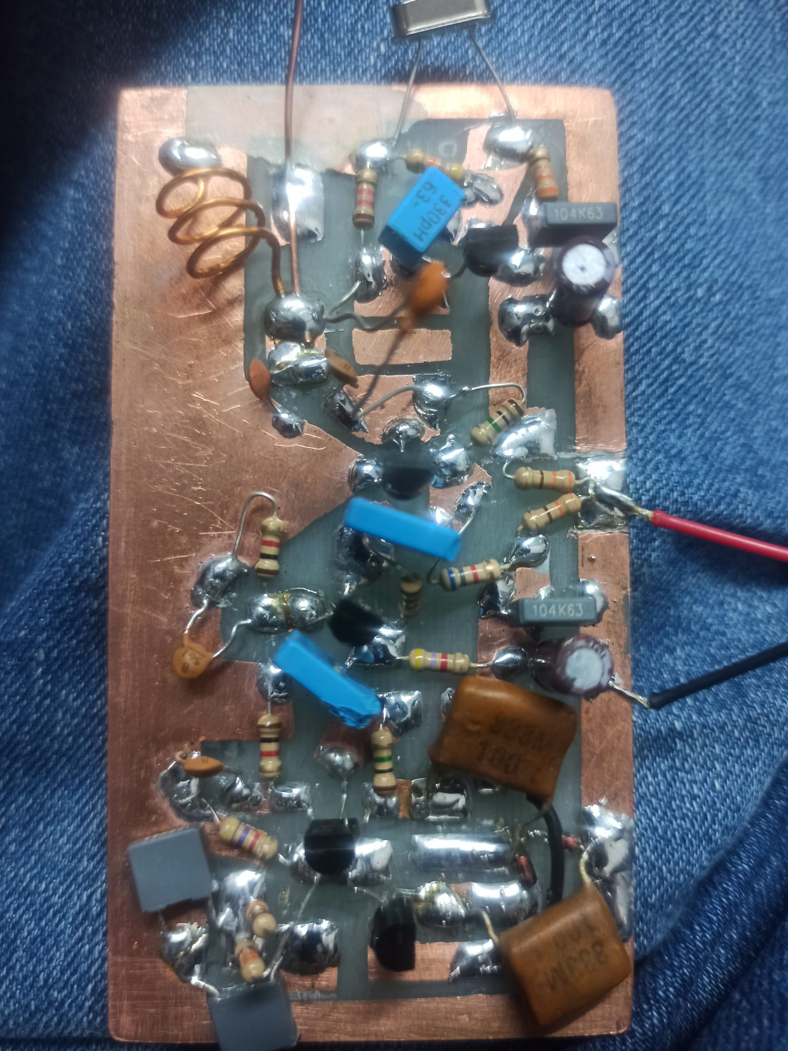
Reply With Quote
  #3189  
Old 04-24-2024, 02:13 PM
FrancoItaly FrancoItaly is offline
Guru
 
Join Date: Feb 2006
Location: Liguria, Italy
Posts: 1,350
Default

My lrl is composed of the sensor stage + the display stage which also provides the stabilized 12V voltage, I attach the version with a LED which also includes the stabilizing part.
Attached Images
File Type: pdf Power display stage(1led).PDF (299.7 KB, 511 views)
Reply With Quote
  #3190  
Old 06-06-2024, 02:43 PM
okantex okantex is offline
Senior Member
 
Join Date: Oct 2005
Posts: 153
Default

Hello Mr Franco
How are you, i hope you are well.
Lrl works with N/S magnetic..ok.
Does it also work through sky effect?
What does sky effect mean for you.
Mixture of locally propageted /available frequencies on the Air?
İf so, can we say that...if our Total antenna reciever is tuned to any of local frequencies ,we will have sky effect Upon elebvating tip of antenna up. İf there is no match to a frequency ,we wont have sky effect..
Can we think in this way , to Check if our lrl is tuned correctly or not?
İn a away ,Franco lrl is a passive reciever like pdk4..pdk is working on frequency matching condition
So, what about Franco?
Francolrl seems like wide band reciver.. residue of any frequency available or mix of them ,will cause increase in receipt Signal. Think like passengers on carrier wagoon..
Just trying to have brain storming of occurance of unknown phenomon
Reply With Quote
  #3191  
Old 06-06-2024, 03:01 PM
FrancoItaly FrancoItaly is offline
Guru
 
Join Date: Feb 2006
Location: Liguria, Italy
Posts: 1,350
Default

Quote:
Originally Posted by okantex View Post
Hello Mr Franco
How are you, i hope you are well.
Lrl works with N/S magnetic..ok.
Does it also work through sky effect?
What does sky effect mean for you.
Mixture of locally propageted /available frequencies on the Air?
İf so, can we say that...if our Total antenna reciever is tuned to any of local frequencies ,we will have sky effect Upon elebvating tip of antenna up. İf there is no match to a frequency ,we wont have sky effect..
Can we think in this way , to Check if our lrl is tuned correctly or not?
İn a away ,Franco lrl is a passive reciever like pdk4..pdk is working on frequency matching condition
So, what about Franco?
Francolrl seems like wide band reciver.. residue of any frequency available or mix of them ,will cause increase in receipt Signal. Think like passengers on carrier wagoon..
Just trying to have brain storming of occurance of unknown phenomon

The phenomenon is very complex, as far as my lrl is concerned the sky effect and the compass effect are eliminated by decreasing the gain. The TR2 mixer has an output, even in the absence of a signal (this is intentional). Any signal that passes the L1/C10 filter modifies the mixer output, so even a signal out of range but very strong (as you said correctly).
Reply With Quote
  #3192  
Old 06-07-2024, 03:08 PM
Kamal Kamal is offline
Junior Member
 
Join Date: Mar 2024
Posts: 11
Default

hello , mr franco .
how to make the antenna sensitive
8 mhz circuit
Reply With Quote
  #3193  
Old 06-07-2024, 03:09 PM
Kamal Kamal is offline
Junior Member
 
Join Date: Mar 2024
Posts: 11
Post

Quote:
Originally Posted by FrancoItaly View Post
The phenomenon is very complex, as far as my lrl is concerned the sky effect and the compass effect are eliminated by decreasing the gain. The TR2 mixer has an output, even in the absence of a signal (this is intentional). Any signal that passes the L1/C10 filter modifies the mixer output, so even a signal out of range but very strong (as you said correctly).
hello , mr franco .
how to make the antenna sensitive
8 mhz circuit
Reply With Quote
  #3194  
Old 06-07-2024, 03:10 PM
Kamal Kamal is offline
Junior Member
 
Join Date: Mar 2024
Posts: 11
Default

Quote:
Originally Posted by FrancoItaly View Post
The 20 Mhz sensor stage is essentially the same as the 8 Mhz version, there are some more adjustments but this makes setup easier, I think you can use the 20 Mhz instead of the 8 Mhz.
hello , mr franco .
how to make the antenna sensitive
8 mhz circuit
Reply With Quote
  #3195  
Old 06-07-2024, 03:45 PM
FrancoItaly FrancoItaly is offline
Guru
 
Join Date: Feb 2006
Location: Liguria, Italy
Posts: 1,350
Default

Quote:
Originally Posted by Kamal View Post
hello , mr franco .
how to make the antenna sensitive
8 mhz circuit
you can try this antenna amplifier suggested by a forum member, the sensitivity increases slightly, at least in my tests. However, the antenna is the same for the 8Mhz and 20Mhz versions.
Attached Images
File Type: pdf antenna amplifier.pdf (293.7 KB, 190 views)
Reply With Quote
  #3196  
Old 06-17-2024, 09:43 AM
okantex okantex is offline
Senior Member
 
Join Date: Oct 2005
Posts: 153
Default

Hello Mr Franco , Omar
Can you tell the condition of sensing sky effect.
What is sky effect .how do we test it
İn my circuit.
At home ,while elevating antenna. Signal goes to max(3leds). But outside of home..no increase .
At home i can not test north south effect.
But outside... At north..45right /45left degree..and same at south .. 1 LED blinks slightly..
Reply With Quote
  #3197  
Old 06-17-2024, 02:11 PM
FrancoItaly FrancoItaly is offline
Guru
 
Join Date: Feb 2006
Location: Liguria, Italy
Posts: 1,350
Default

Quote:
Originally Posted by okantex View Post
Hello Mr Franco , Omar
Can you tell the condition of sensing sky effect.
What is sky effect .how do we test it
İn my circuit.
At home ,while elevating antenna. Signal goes to max(3leds). But outside of home..no increase .
At home i can not test north south effect.
But outside... At north..45right /45left degree..and same at south .. 1 LED blinks slightly..
The sky effect and compass effect are only noticeable outside and appear when there is too much amplification, inside there is too much electromagnetic disturbance.
Reply With Quote
  #3198  
Old 06-24-2024, 04:59 PM
okantex okantex is offline
Senior Member
 
Join Date: Oct 2005
Posts: 153
Default

Mr Franco
for the message 3125
you are saying in all formations(L1 C10 options) reception of antenna is in 80/120mhz
I would like to ask.. when you are outside.. and when you elevate antenna stick to sky 90 degree..does your first led or all starts giving lights..and buzzer beep?

at outside even adjusting all pots for max values.. ( I have 2 bobin version with12mhz lm3914 10 leds..) just see 3/4 leds..nothing changes while elevating antenna up..can not see sky effect.
with this setup..I have pointed few places with 6 to10 leds..
not all pots are not max.. in north direction..I am calibrating with first led and sink it..then I can searh in north south directiion...
even at my pointed targets with 6-10 leds on.. I can not get signal from east or west..
I feel that I am not recieving in FM range..if I were .... whereever I elevate antanna up. , I have to see radio waves..
without antenna input. my tr5 output.. or 358 input.. is around 5 volts

I would like to have comments of you , and Erfan and Omar
thanks for advices

I think we are traching by reclections of north south.......compass effect...magnetic lines of earth..,and for other all directions.. reflections of available RF propagations...mostly

I feel I am just receiving ghz of wifi at building..

one another poing.. I am using battery 12V instead of 2x9Vcells.
I am not using regulator...
when I am touching to battary signal is decreasing.. as you touch to antenna..

you have advised to use secondary cooper not etched..as screen. and do connection to GND from screen.. if I am wrong for give me... for aluminium boxes.. do connection to box from gnd.. also use aluminium Rod and connect to gnd..
I am testing it by touching to GND of battery.. it is same..I think..
results signal sinks..
Reply With Quote
  #3199  
Old 06-25-2024, 12:43 AM
omar omar is offline
Member
 
Join Date: Apr 2021
Posts: 78
Default

Hello,

I made two versions of the Franco device a long time ago, the 8 MHz version... one with a BC547 transistor that does not sense the sky, and the second with a BC173 transistor. It was good according to the required specifications and senses the sky...

and I remember that one of the problems I found in the real field was the need to reset the threshold frequently because Rapid sensitivity collapse. Also, the signal is not fixed at the same point at all times. The thing that I did not really know is that the signal depends on the surrounding conditions, place and time....

I advise strict adherence to Franco?s scheme as it is, without more or less. Three LEDs are sufficient to track and know the level of the signal. Using additional accessories that may cause confusion for the user....

For example,,,, I have done By adding a protection diode to Franco's circuit, and when I simulated the circuit, this diode caused sensitivity problems. Using regular batteries is better than lithium or acid charging batteries because of the voltage noise...

and also self-oscillation. I noticed it with several sensitive receiving circuits. Why it happens I do not know definitively, although you use the same parts on the breadboard once you succeed with no self-oscillation and the same parts return. Assembling it again, you find it suffers from self-oscillation. Using ceramic capacitors is better because of their faster signal interruption and small capacitance.

Stable operating voltage in such sensitive circuits (very, very important). The use of a voltage regulator is mandatory, to stabilize circuit operation and sensitivity.
Reply With Quote
  #3200  
Old 06-25-2024, 06:41 AM
okantex okantex is offline
Senior Member
 
Join Date: Oct 2005
Posts: 153
Default

When there was 7812 with 12v acid battery.
There Signal at display stage .even sens?r stage was Stable alone. İ deteched stages..but could not lose osilation. İ could let it work after detaching 7812..
Btw, i am also using protection diode at positive entrance..i frequently do wrong connection and burn circuit.
İs not protection a kime of regulator for supply line

Now i do not have osilation..and circuit is Stable.
But it detects me from battery.
But my observation is that..if we dongnd )shild/holder connections...webare decreasing signal.
Reply With Quote
Reply


Posting Rules
You may not post new threads
You may not post replies
You may not post attachments
You may not edit your posts

BB code is On
Smilies are On
[IMG] code is On
HTML code is Off

Forum Jump


All times are GMT. The time now is 04:23 PM.


Powered by vBulletin® Version 3.8.11
Copyright ©2000 - 2024, vBulletin Solutions Inc.