
|
|
|
|
#1
 02-12-2016, 01:33 PM
|
||||
|
||||
|
Hi enjoykin
I need some explanations about Tabletka Korobeinikova experimet you posted in another thread. Schematic parts is clear, not so photo you posted. So - Questions: 1. Is equipment (configuration) present in photos all what we need for Tabletka Korobeinikova experiment? 2. In what function is used AVO meter present in photo. Is AVO meter set as signal generator to drive (buffer) transistor from schematic? 3. In what function is used amateur radio transceiver present in photo? Is this transceiver set as receiver to prove that signal is coming out of Faraday shielded Tabletka Korobeinikova? 4. At what frequency experiment Tabletka Korobeinikova from photo was carried out? 5. What was distance from Tabletka Korobeinikova and testing receiver?  
__________________
Global capital is ruining your life? You have right to self-defence! 
|
|
#2
02-13-2016, 12:39 AM
|
|||
|
|||
|
Hello WM6
For best valuable informations about HZ antenna or "tabletka Korobeinikova" you can contact author  Коробейников Владимир Иванович 194354 г.Санкт-Петербург Учебный пер. 6 кор.1 кв.198, т.(812) 511-18-77, E-mail: elen (at) mail.infos.ru Here are couple of his articles in Russian QRZ.RU Магнитные антенны для сверхдальней радиосвязи http://www.qrz.ru/schemes/contribute/antenns/eh/ Правда и вымысел EH-антенн http://www.qrz.ru/articles/detail.phtml?id=282 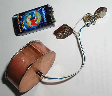 Example of Tabletka Korobeinikova for 100 MHz ps: His antenna work but his physical theory is not correct. Correct theory for scalar antennas you can find in lifework of Professor Gennadiy Vasilevitch Nikolaev. Советую попробовать, не пожалеете! Удачи и 73 !!!! 
|
|
#3
02-13-2016, 12:53 AM
|
|||
|
|||
|
So - The Answers:
1. Is equipment (configuration) present in photos all what we need for Tabletka Korobeinikova experiment? 1A. NOT 2. In what function is used AVO meter present in photo. Is AVO meter set as signal generator to drive (buffer) transistor from schematic? 2A. NOT 3. In what function is used amateur radio transceiver present in photo? Is this transceiver set as receiver to prove that signal is coming out of Faraday shielded Tabletka Korobeinikova? 3A. Fuction was to work as hi was designed - as transceiver. There are two amateur radio transceivers both modified to use antenna Korobeinikova not factory antennas. 4. At what frequency experiment Tabletka Korobeinikova from photo was carried out? amateur radio band 144Mhz. 5. What was distance from Tabletka Korobeinikova and testing receiver? There were many different tests and diferent distances. One of them was underwater test from the lake bed near S.Peterburg - which have proved that signal has came from deep underwater (i think was 6-8 meters). Best regards enjoykin4
|
|
#6
02-13-2016, 06:48 AM
|
|||
|
|||
|
WM6 on same principles work Scalar underground radio X-FERRA
http://www.xferra.com/products/ 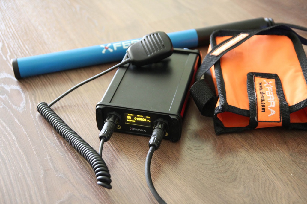  The system «Xferra» has been designed by scientists of the research-and- production company «HF communication» with support of Foundation for Assistance to Small Innovative Enterprises (FASIE) and the Omsk region Government. «HF communication», xferra@mail.ru, +7 3812 292464 Kharkovskaya str. 23 office 123, Omsk, 644041, Russia http://www.xferra.com
|
|
#7
02-13-2016, 12:06 PM
|
||||
|
||||
|
Quote:
I will carry out some tests in this field in near future. Will report back.
__________________
Global capital is ruining your life? You have right to self-defence!
|
 |
|
|


 Hybrid Mode
