
|
|
#1
 11-28-2012, 01:52 AM
|
||||
|
||||
|
If one need a 70kHz transmitter with exact frequency, I suggest this solution:
1. Use this module from eBay ($38 + free shipping): 0.01- 5MHz DDS Function Signal Generator Module  http://www.ebay.com/itm/0-01-5MHz-DD...-/270864768941 2. Signal generator has enough amplitude to act as transmitter you need, but if you insist that you need more power, then connect signal generator to this module from eBay: Mono 25W Audio Amplifier Module Board, Based on LM1875 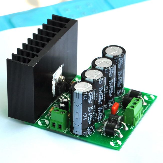 http://www.ebay.com/itm/Mono-25W-Aud...item5d30720799 Do not drive it with full power - 1/10 of max power, no more. Inductance of antenna (ferrite core or air core - the last one is better) have to be about 50mH. Exact value depend of antenna windings stray capacitance. You need to connect antenna instead of loudspeaker. Of course this transmitter can generate any other arbitrary frequency too (for some very different antenna inductance need to be recalculated). Use sine wave.
__________________
Global capital is ruining your life? You have right to self-defence! 
|
|
#2
11-28-2012, 05:30 AM
|
||||
|
||||
|
tank you very much freind
I have a problem in calculating the period number and size of the ferrite coil.Get tips on how to calculate the winding.If there is a formula to give. If I have a signal generator, and can help to strengthen the ferrite Can I send a wave? How? tanks ubram
|
|
#3
11-28-2012, 10:47 AM
|
||||
|
||||
|
Quote:
You need to wind 10 (or better 20 or 30) testing turns of wire (diameter about 0.3 or so) on ferrite rod antenna you have. Then measure inductance. Par example: If you wound 30 testing turns and then measured inductance is 15mH, then you calculate total turns this way: 30 / 15 = 2 This mean that you need 2 of turns to get 1mH. To get 50mH you need 50x2(turns)=100 (turns). So you need 100 turns in total on your ferrite rod to get 50mH ferrite cored antenna. Ferrite cored transmitter antenna is not the best solution for TX, air cored antenna is better. Of course it depend of what you need and what you try to build. If you need "shielded" (i.e. mounted in a tin can) antenna (to radiate in one direction) ferrite core antenna can be better solution than air core.
__________________
Global capital is ruining your life? You have right to self-defence!
|
|
#4
11-28-2012, 11:21 AM
|
||||
|
||||
|
Quote:
|
|
#5
11-28-2012, 12:14 PM
|
||||
|
||||
|
Here proposed TX configuration can be used till to 150kHz, even more. Of course not with same antenna specifications given here.
For frequencies 70kHz +-10kHz antenna even do not need to be recalculated.
__________________
Global capital is ruining your life? You have right to self-defence!
|
|
#6
11-28-2012, 06:58 PM
|
||||
|
||||
|
Quote:
Is the ferrite core and reflector antennas can be directly sent 70kh frequency? Frequency of 70 kHz with a transmitter power is enhanced to within 50 meters sent? Changes in the frequency or electromagnetic radius of 50 meters on the ground with metal?in coil ANTENNA and ferrite core?
|
|
#7
11-30-2012, 11:02 AM
|
||||
|
||||
|
Quote:
__________________
Global capital is ruining your life? You have right to self-defence!
|
|
#8
05-10-2013, 12:13 PM
|
||||
|
||||
|
Hello Barbarossa, this can be your solution. First use signal generator to check your GG receiver exact frequency, then use the same to build TX stage working at the same frequency. Use round or square antenna so you can play with TX wave propagation (polarization) combined with proper TX distance.
__________________
Global capital is ruining your life? You have right to self-defence!
|
|
#9
05-10-2013, 01:04 PM
|
|||
|
|||
|
Just a quick note. Those frequency generators are rejects. They did not pass the quality standards. You pays your money and you takes your chances.
|
|
#10
05-10-2013, 01:44 PM
|
||||
|
||||
|
Quote:
If you can find something better and more precise (look at data below) for $38, then please tell us: Frequency range:0.01Hz ~5MHz(SG1005) Resolution:0.01Hz Frequency Stability:±1×10⁻⁶ Frequency accuracy:±5×10⁻⁶ Sine wave distortion:≤0.8% (reference frequency is 1kHz)
__________________
Global capital is ruining your life? You have right to self-defence!
|
|
#11
05-10-2013, 03:11 PM
|
|||
|
|||
|
I speak from first hand experience, so yes I guess it is from Mike(Mont)'s lab.
|
|
#12
05-11-2013, 02:21 PM
|
|||
|
|||
|
Sorry, posted this on the wrong thread.
I'm not saying the chip is bad. It's the hardware/controls that is the weak link.
|
|
#13
05-17-2013, 05:58 AM
|
||||
|
||||
|
Hi WM6.
I need something like your schematic for an experiment to locate caves. I must use a wire 150 ... 200m as antenna and at the end it will be grounded. Have you any program to calculate the antenna resistance so to match it with the amplifier?? Regards 
__________________
Geo
|
|
#14
05-17-2013, 07:20 AM
|
||||
|
||||
|
Quote:
You mean end of air cored coil antenna cold wire end connected to circuit ground (similar as on block schema in my first post but without ferrite core) or straight antenna wire end grounded in soil? In second case (straight antenna wire end grounded in soil) there is no way to proper adapt resistance of 150m wire at VLF band to your amplifier output. But if you insist on this configuration, forget resistance and drive your amplifier at max 25% of its power. Another solution is to use (for <30khz band) an old speaker transformer (for 4-8 ohm speakers) connected in reverse to amplifier (Warning: high voltage at output!) and max. 50% of amp. power. For higher frequencies use ferrite transformer (if you build one on bigger ferrite toroid primary have to be 4 ohms and secondary windings at your wish - say 50Vpp to not be dangerous). In first case (air cored coil antenna cold wire end connected to circuit ground) you chose antenna resistance according technical specification of amplifier you use, which is in amplifier from post above about 4 Ohms or a little more. You do not need special antenna tunning (SWR) as on HAM bands. Never drive your amplifier at more than 75% of max power.
__________________
Global capital is ruining your life? You have right to self-defence!
|
|
#15
05-17-2013, 12:06 PM
|
||||
|
||||
|
Quote:
2...3 watts maybe is enough Regards
__________________
Geo
|
|
#16
05-17-2013, 08:57 PM
|
||||
|
||||
|
Quote:
As I say, I prefer air cored coil antenna (unshielded of course), but for distances of 10-30m ferrite cored antenna can be usable too. Proper distance from detecting place is achieved when antenna polarization (changing orientation of antenna in different directions) can give you very clear differences in signal strength on field strength meter (receiver).
__________________
Global capital is ruining your life? You have right to self-defence!
|
|
#17
05-18-2013, 04:50 AM
|
||||
|
||||
|
Quote:
I want to receive the signal with 2 loops with 90 degrees phase shift between them and to measure the phase shift.
__________________
Geo
|
|
#18
05-18-2013, 10:57 AM
|
||||
|
||||
|
Quote:
Are you talking about two TX antennas?
__________________
Global capital is ruining your life? You have right to self-defence!
|
|
#20
05-19-2013, 05:27 AM
|
|||
|
|||
|
Geo, that patent is a hybrid between "VLF geophysical" and Turam apparatus. It is for geophysical mapping and doesn't have anything to do with "LRL's" which (as everyone knows) is a designation for fraudulent apparatus. Not much use for detecting individual coins either- it circumvents the "rule of 64" that's been discussed recently on the Geotech "coils" forum, but pays the price of having done so.
If you are interested in constructing something according to that patent, this is the wrong forum, I highly recommend Geotech where there are a few people who actually understand this kind of stuff. This is the LRL forum. If you expect technical help from the likes of Montana and Hung and Dell, you already know from them in their own words what kind of company you're keeping. By their own frank admission they don't know squat about electronics or physics, would you trust either one of 'em to change a burned out light bulb? Oddly enough, they regard their admitted ignorance as a defense! of their products! "Skeptics" don't have to make this incredible nonsense up, my slogan "read the advertisement" is a solidly paved road to the truth of the matter. Who posts links to Mineoro's website? It's me, not Hung! We obviously know the same thing about what's to be found there. Mineoro's own website and promoters' forum posts are the best source we've got for evidence of fraud to be made public. It's why people like me have argued in favor of allowing LRL fraudsters to say their piece, even when they're "marketing", something that's usually forbidden on forums. I say let the criminals and delusional incompetents be given the opportunity to confess to what they are, and that's something they do well. Geo, I don't know your educational background. This is an enterprise where without high school level physics and math as well as practical knowledge in electronics, you're doomed. (That's why they teach this stuff in public schools-- so those who find the subject matter interesting won't be doomed.) One of my very well-educated co-workers just took a grad level University course in this stuff and found it challenging, but thankfully earned an A in the course. Thanks in part to my abundant file material on the subject, something to which the other students had no access. After all, the physics basics have been kicking around for something like 100 years, it is only the technical ability to achieve improvements in performance of practical products that has changed. The first patent on a VLF induction balance discriminator for ID'ing coins dates back to the late 1800's, before "electronics" even existed, it was just electricity. The patented device was a bench model for use by banks to detect counterfeit coins, but the physical principles haven't changed, any modern metal detector engineer would immediately recognize it for what it was. ....Sorry, I don't have the patent number, but the thing really existed, a few years ago I printed it out, but sorry, I don't know what file I stuck it in. No majick, just creative use of the technological possibilitities that presented themselves at that time. And, that was an extraordinarily creative period of scientific-technological endeavor, it created the modern world as we now know it. --Dave J.
|
|
#21
05-19-2013, 10:52 AM
|
||||
|
||||
|
Dave, thanks for your reply.
1. When we speak about lrl you find me opposite because i found many objects with lrls. Also i found objects with simple gamma dowsing rods, but the thread is not this. 2. The thread is the pattent US4079309 for cave location. I have read this pattent very well and when i"ll find free time (maybe on September) i want to experiment with it. I have study as electronic and electrician engineer but now i work only at my farm as farmer: Θυμωμένος:. It is easy for me to construct two lf receivers and to measure the phase shift between them. The transmitter also is not problem The problem as you know is how to make all them to work harmoniously between them. Sorry because i write so little.... but my bad English don't allow me to write more or i need more time to looking at dictionary for the right words. Regards
__________________
Geo
|
|
#22
05-19-2013, 07:19 PM
|
||||
|
||||
|
HI WM6
ONE QUESTION: The output frequency range is changed after colliding with metal remote?Measurable change in the circuit? What is the frequency range of the earth?FOR EXAMPLE: KHZ OR MHZ OR EXAMPLE MAXIMUM 100KHZ? MHz frequency range to penetrate the soil? G.L
__________________
 Knowledge is the greatest wealth Knowledge is the greatest wealth
|
|
#23
05-20-2013, 01:29 PM
|
||||
|
||||
|
Quote:
1. If we are speaking of reflection, there is no change in reflected frequency, but depend of frequency (wavelength) you can expect some changes in phase and polarization of reflected wave. 2. It is not clear if you asking for frequency range of soil (earth) or frequency range of Earth (our planet)? Soil is not unique matter so its frequency range cannot bi expressed in one single frequency. Earth specific frequency was given already by Nikola Tesla in his energy "teleportation" patents and experiments and it is about couple of Hertz. 3. UKW (MHz) range of frequencies is relatively poor penetrator in sol, in comparisons to VLF, but is still usable (as compromise between penetration and portable and directive antennas constructibility) in GPR devices. If you need deep soil penetration then use frequency of about 2kHz, but you will lose sensitivity to small things like tiny gold nuggets. But probably you know all this.
__________________
Global capital is ruining your life? You have right to self-defence!
|
|
#24
08-03-2013, 09:27 AM
|
||||
|
||||
|
Quote:
Have a look for 2 Schematics ( I have made them) they work just fine separately !! I didnt try them to to cooperate together maybe they will help you !! VLF Transmitter : http://postimg.org/image/58d44lkpv/ Tracer Receiver : http://postimg.org/image/t23g3xo8n/ and pay attention what WM6 said : If you need deep soil penetration then use frequency of about 2kHz, but you will lose sensitivity to small things like tiny gold nuggets. ( if you use a crystal about 10 Mhz at Q12 :4096 for 4060 it will gives you a Frequency about 2Khz !!! Regards epitopios and .... 73s
|
 |
|
|


 Linear Mode

