 |
|
#1
|
|||
|
|||
 This is a simple absorption metal detector circuit, but I believe that with some modifications to make a good LRL, mineoro's fg also have an oscillator in the resonant input circuit. With a suitable coil, the device will detect old metals in which the hallo effect is present. The oscillator circuit works with a very low current, so that the magnetic field is as little as possible, and that in the presence of metals a part of this magnetic field is stolen from the coil, reducing the wave amplitude, that alone was good, more it was possible to amplify this signal even more, so that it can function as a sensitive low frequency receiver, where if it had some radiated signal, it would be mixed with the signal of this oscillator that would later be demodulated and amplified again, having as a final sensitive receiver, which could pick up some anomaly in the distance. https://makingcircuits.com/blog/ferr...etal-detector/ |
|
#2
|
|||
|
|||
|
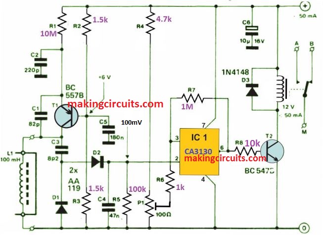
The design of the Colpitt?s Oscillator has been depicted in figure above. This oscillator works at a frequency that is near about 70 kHz. L1, i.e. the inductor also works as the sensor. The Oscillator, R1 only works at the high value of the emitter resistor.
This is a desirable value, otherwise the transistor will replenish any losses in the tuned circuit. D1 and D2 rectify the output of the oscillator. The resulting direct voltage works to the inverting input of Schmitt trigger, i.e. IC1. However, decrease of that voltage below the desired level at pin 3 (present by P1), the output becomes logic high, therefore energizing the relay. However, it is unfortunate that one cannot get this ready-made. L1, i.e. the inductor is not intended to be set on the circuit board. This is a standard non-screened choke of 100 mH. How to Test When the oscillator does not automatically start at setting of P1, the value of R1 has to be reduced to make it work out. However, if the oscillator refuses to stop working when a metal object is placed near L1, R1?s value must be put on higher side, in that case. The stated value of R1 could be found exactly when L1 is of Toko type. Starting with the wiper of P1 to earth, the present must be adjusted. This will prevent the relay from operating. Advance the wiper a bit further, if it requires a lower sensitivity. The determination of current consumption is based on if the relay is energized or not. However, it must not be greater than 50mA. |
|
#3
|
|||
|
|||
|
In my opinion the amplification is too low, on the other hand with this circuit solution it is not possible to do more.
|
|
#4
|
|||
|
|||
|
Quote:
Depending on the colpitts oscillator configuration, it is possible to have a mixing of the local oscillator signal, and any signal that is radiating at the site, taking advantage of the same coil, is what was implemented in mineoro 08MI's two-box detector.  https://i.ibb.co/tKLh3qR/mineoro-08mi.jpg In this mining circuit, the amplitude in the search coil is around 75mV peak to peak, this signal will have practically the same amplitude in the emitter of the transistor, which is where the signal to be amplified comes out. The resistors in the collector are just there so that you have a low amplitude wave generated by this oscillator. With this low amplitude it is possible to amplify this local oscillator signal together with the search signal that you want to search for more than 100 times yet, without being mowed down. It may seem a little bit of amplification, but this is just the RF amplification, because after the signal is demodulated and filtered, it will result in a low frequency signal, and also a low amplitude one, which will be amplified many times yet, and it is that's where the secret is. As a final result we will have a tuned receiver of high sensitivity, which will still be able to detect metals. |
 |
|
|