LongRangeLocators Forums  

Go Back   LongRangeLocators Forums > Main Forums > All-Electronic LRLs

Reply
 
Thread Tools Display Modes
  #126  
Old 12-30-2023, 04:41 PM
omar omar is offline
Member
 
Join Date: Apr 2021
Posts: 86
Default

https://www.raed.net/file?id=563004
Reply With Quote
  #127  
Old 12-30-2023, 06:33 PM
aft_72005's Avatar
aft_72005 aft_72005 is offline
Guru
 
Join Date: Feb 2005
Location: The empire of Cyrus the great...Iran
Posts: 772
Default

Quote:
Originally Posted by omar View Post
Thank you.
Reply With Quote
  #128  
Old 12-30-2023, 08:15 PM
omar omar is offline
Member
 
Join Date: Apr 2021
Posts: 86
Default

You're welcome. Good luck
Reply With Quote
  #129  
Old 01-08-2024, 05:58 PM
Yusufyaba Yusufyaba is offline
Junior Member
 
Join Date: May 2023
Posts: 23
Default

Quote:
Originally Posted by omar View Post
You're welcome. Good luck
hello omar
I made an application suitable for your project but with pcb holes. I could not solve the LED situation. It seems to work. There is detection as the tx power is reduced and the frequencies change. It is a workshop environment, not a natural environment.
Reply With Quote
  #130  
Old 01-08-2024, 08:01 PM
omar omar is offline
Member
 
Join Date: Apr 2021
Posts: 86
Default

Frankly, this modification needs the support of someone who has successfully tried the device with a similar modification. For example, how much transmission power is appropriate for capacitively coupling the coils with the ability to balance and adjust the threshold. Is shielding the sensing phase binding? What is the correct direction of the current in the two coils? presented to you the idea and the path others took in developing it, and it seems that they succeeded in the operation process. Now it's up to you to try it. I hope that whoever succeeds with this amendment will help the rest of the members.
Reply With Quote
  #131  
Old 01-10-2024, 04:13 AM
Anwar2 Anwar2 is offline
Member
 
Join Date: Sep 2011
Posts: 33
Default

Quote:
Originally Posted by omar View Post
Frankly, this modification needs the support of someone who has successfully tried the device with a similar modification. For example, how much transmission power is appropriate for capacitively coupling the coils with the ability to balance and adjust the threshold. Is shielding the sensing phase binding? What is the correct direction of the current in the two coils? presented to you the idea and the path others took in developing it, and it seems that they succeeded in the operation process. Now it's up to you to try it. I hope that whoever succeeds with this amendment will help the rest of the members.
hello Omar imade this TOTEM but its prduce the 65khrz frequincy but i cant balance tx and rx its work with sparks need some one show as by vedio how to balance it imade:https://youtu.be/9xdu1eedKZk
Reply With Quote
  #132  
Old 01-10-2024, 02:48 PM
aft_72005's Avatar
aft_72005 aft_72005 is offline
Guru
 
Join Date: Feb 2005
Location: The empire of Cyrus the great...Iran
Posts: 772
Default

Hi

does the totem really work in practice as a long range.. Has anyone discovered old metal with the totem?
there isn't any report totem work as long range

Reply With Quote
  #133  
Old 01-10-2024, 03:53 PM
abdou2014 abdou2014 is offline
Guru
 
Join Date: Mar 2014
Posts: 1,024
Default

must change the TX circuit
Reply With Quote
  #134  
Old 01-10-2024, 09:12 PM
aft_72005's Avatar
aft_72005 aft_72005 is offline
Guru
 
Join Date: Feb 2005
Location: The empire of Cyrus the great...Iran
Posts: 772
Default

Quote:
Originally Posted by abdou2014 View Post
must change the TX circuit
totem TX without problem .. why transmitter must change ?
Reply With Quote
  #135  
Old 01-11-2024, 01:09 PM
omar omar is offline
Member
 
Join Date: Apr 2021
Posts: 86
Default

Quote:
Originally Posted by aft_72005 View Post
Hi

does the totem really work in practice as a long range.. Has anyone discovered old metal with the totem?
there isn't any report totem work as long range


Hello my friend .
Anyone who wants to try this device.
First, he must make a receiving circuit with only the receiving coil and test the device according to the operating instructions in the file attached to the first post in this topic, such as sensing the electric spark... etc. After making sure your device works very well and there are no problems or errors in assembly or parts. You go to the second step, which is manufacturing the transmission circuit and adding it to the receiver. I do not advise anyone to manufacture this device, but there are people who want to try this device (for them I am providing this information) to help them and make things easier for them and to make the appearance of the device more dynamic and acceptable. Because I think something useful can come out of this device. I will post pictures and links explaining my idea regarding the device?s narrow-band antenna. And manufacturing methods.


https://youtu.be/9gjUlqH9dTQ?si=ZddyPDx97yvPaMZF


I wish everyone good luck and thank you
Reply With Quote
  #136  
Old 01-11-2024, 06:28 PM
aft_72005's Avatar
aft_72005 aft_72005 is offline
Guru
 
Join Date: Feb 2005
Location: The empire of Cyrus the great...Iran
Posts: 772
Default

Hi omar
yes , i agree with your opinion . but i remember my experiments for some years ago Tx and Rx on ferrite couldn't act as long range.
Reply With Quote
  #137  
Old 01-11-2024, 06:37 PM
aft_72005's Avatar
aft_72005 aft_72005 is offline
Guru
 
Join Date: Feb 2005
Location: The empire of Cyrus the great...Iran
Posts: 772
Default

may be designer of totem had feedbacks from people that built and trying totem .
Reply With Quote
  #138  
Old 01-12-2024, 04:25 PM
Anwar2 Anwar2 is offline
Member
 
Join Date: Sep 2011
Posts: 33
Default

Quote:
Originally Posted by omar View Post
thanks Omar this one is defrent than TeTOM in this one RX and TX are in one frett road
and how long the freet road in this one.?.
in last tow day
i make ready the circuit
Attached Images
 
Reply With Quote
  #139  
Old 01-12-2024, 04:40 PM
Anwar2 Anwar2 is offline
Member
 
Join Date: Sep 2011
Posts: 33
Default

thanks how to delet this message
Reply With Quote
  #140  
Old 01-12-2024, 04:58 PM
omar omar is offline
Member
 
Join Date: Apr 2021
Posts: 86
Default

I apologize to you, my friend Anwar.
I did not understand your problem. I placed the drawing files open so that members could change as desired. The device does not accept calibration. You may need to flip the transmission coil (change the direction of the field), or the transmission power is high and needs to be reduced and the resistance value increased by 1 K.
Reply With Quote
  #141  
Old 01-12-2024, 05:16 PM
Anwar2 Anwar2 is offline
Member
 
Join Date: Sep 2011
Posts: 33
Default

Quote:
Originally Posted by omar View Post
I apologize to you, my friend Anwar.
I did not understand your problem. I placed the drawing files open so that members could change as desired. The device does not accept calibration. You may need to flip the transmission coil (change the direction of the field), or the transmission power is high and needs to be reduced and the resistance value increased by 1 K.
thanks my friend Omar sorry for destorb acualy My son Name Omar I like your Name
Reply With Quote
  #142  
Old 01-12-2024, 05:21 PM
Anwar2 Anwar2 is offline
Member
 
Join Date: Sep 2011
Posts: 33
Default

Quote:
Originally Posted by omar View Post
I apologize to you, my friend Anwar.
I did not understand your problem. I placed the drawing files open so that members could change as desired. The device does not accept calibration. You may need to flip the transmission coil (change the direction of the field), or the transmission power is high and needs to be reduced and the resistance value increased by 1 K.
thanks
Reply With Quote
  #143  
Old 01-12-2024, 05:39 PM
omar omar is offline
Member
 
Join Date: Apr 2021
Posts: 86
Default

Don't worry, my friend Anwar. I know the amount of effort it takes to create a device manually, the challenges with this type of device, and the disappointment when it does not work the first time. Or even when it works and its feasibility is discovered much less than expected, it is hope that makes us try and try. I wish you success in your life and abundant livelihood.
Reply With Quote
  #144  
Old 01-13-2024, 04:28 AM
Anwar2 Anwar2 is offline
Member
 
Join Date: Sep 2011
Posts: 33
Default how to connect the test point

how to connet the test point I think with press switch and Ground
Attached Images
 
Reply With Quote
  #145  
Old 01-13-2024, 08:59 AM
omar omar is offline
Member
 
Join Date: Apr 2021
Posts: 86
Default

This frequency measuring point is connected to an external device called a frequency meter. To adjust the transmitter frequency
Reply With Quote
  #146  
Old 01-13-2024, 09:54 AM
Anwar2 Anwar2 is offline
Member
 
Join Date: Sep 2011
Posts: 33
Default

Quote:
Originally Posted by omar View Post
This frequency measuring point is connected to an external device called a frequency meter. To adjust the transmitter frequency
thanks Omar between RX there is acapacitor on the PCB What value of that
Reply With Quote
  #147  
Old 01-13-2024, 05:22 PM
omar omar is offline
Member
 
Join Date: Apr 2021
Posts: 86
Default

Capacitor value with coil inductance. Determined by the frequency at which you will operate. I advise you to use the original transmission scheme, as its value is set to 65 kHz. Especially if you are using the original version. Note that not all 555 timers provide a stable frequency depending on the quality of manufacturing.
Reply With Quote
  #148  
Old 01-15-2024, 07:09 AM
Anwar2 Anwar2 is offline
Member
 
Join Date: Sep 2011
Posts: 33
Default

Quote:
Originally Posted by omar View Post
Capacitor value with coil inductance. Determined by the frequency at which you will operate. I advise you to use the original transmission scheme, as its value is set to 65 kHz. Especially if you are using the original version. Note that not all 555 timers provide a stable frequency depending on the quality of manufacturing.
yes omar your correct not all 555 timer provide the same frequency .. thanks my friend
Reply With Quote
  #149  
Old 01-22-2024, 02:49 PM
manos manos is offline
Junior Member
 
Join Date: Mar 2023
Posts: 2
Default

Hi tell us some information about ferrite coils
Reply With Quote
  #150  
Old 02-20-2024, 03:15 PM
manos manos is offline
Junior Member
 
Join Date: Mar 2023
Posts: 2
Default

Quote:
Originally Posted by Anwar2 View Post
how to connet the test point I think with press switch and Ground
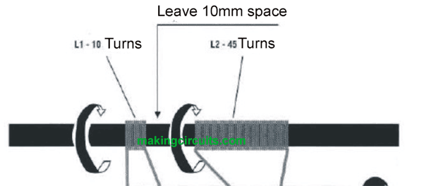
Hi how many turns is the coil TX and the RX in ferrite and the .mm of the wire, thanks
Reply With Quote
Reply


Posting Rules
You may not post new threads
You may not post replies
You may not post attachments
You may not edit your posts

BB code is On
Smilies are On
[IMG] code is On
HTML code is Off

Forum Jump


All times are GMT. The time now is 02:18 AM.


Powered by vBulletin® Version 3.8.11
Copyright ©2000 - 2024, vBulletin Solutions Inc.