LongRangeLocators Forums  

Go Back   LongRangeLocators Forums > Main Forums > Long Range Locators

Reply
 
Thread Tools Display Modes
  #26  
Old 01-26-2012, 07:20 PM
J_Player's Avatar
J_Player J_Player is offline
Guru
 
Join Date: Feb 2006
Location: California
Posts: 4,382
Default

Quote:
Originally Posted by michael View Post
Hi dear J-P.
my e.e friend had given it to me. I had it for few months.
it was a small box with a small display for digits and had 2 type sensor; one type was for receiving air waves that got and antenna, in this option it couldn't get any signal from soil or with connection to ground.
Another sensor type had 2 output for 2 wires with alligator head which connected to wave source( MFD probes). in this option it couldn't get any signal from air
as I had tested it frequently; both wires should be connected to somewhere.

In the test which I mentioned above I personally made it with wires( I call it ground mode). m
It was essential for me to know if these kind of waves ( radio) generated by a MFD could ever travel through ground or not.
so I plugged each alligator into an iron rod and planted in ground and as mentioned could get signal up to 2 meters beyond not more.
Unfortunately I don't know more about that device technical details. just knowy friend called it " portable frequency meter".
Thank you michael,
This is good information to know.
From what you say, you were using a Notsi Mole LRL 2000D frequency generator to make the signal for ground probes, and a portable frequency counter to detect the signal.
According to the Notsi literature, this frequency generator uses two 12v batteries, and a micro controller to create the frequency. They don't really say what maximum voltage is put out (probably is less than 24v), but it says you can control the voltage, and it can reach a distance of 5Km and 60 meters deep into the ground. It also does not say what frequency range it sends out, but it has 6 frequencies programmed for lead, gold, aluminum, silver, brass, bronze, diamonds and iron. Also you can program 7 of your own frequencies.

I am guessing the frequency meter you used is a portable battery operated frequency counter that has an aerial antenna and two test probes with alligator clips, that do not have a shield.
From what you say, you got no signal except when you tried at a way you call ground mode.
I have difficulty to understand how you connected the two alligator clip leads.
From what I read it sounds like you dropped both alligator clip wires into a vase that you buried in the ground.
It seems like there are too many details missing for me to determine what the signal path was exactly.
But I believe you made some detection at the distance you say.
Maybe if we learn the voltage and frequency at the MFD probes and the distance they were set apart, and exactly where each of the two frequency counter probes were connected to, we would have some idea how to make a similar test.

Also, as I recall, the ground moisture changes the detection distance too.

One question:
Did your Bulgarian locator work to locate any treasures?


Best wishses,
J_P
Reply With Quote
  #27  
Old 01-27-2012, 11:47 AM
michael michael is offline
Guru
 
Join Date: Nov 2005
Posts: 561
Default

Quote:
Originally Posted by J_Player View Post
Thank you michael,
This is good information to know.
From what you say, you were using a Notsi Mole LRL 2000D frequency generator to make the signal for ground probes, and a portable frequency counter to detect the signal.
According to the Notsi literature, this frequency generator uses two 12v batteries, and a micro controller to create the frequency. They don't really say what maximum voltage is put out (probably is less than 24v), but it says you can control the voltage, and it can reach a distance of 5Km and 60 meters deep into the ground. It also does not say what frequency range it sends out, but it has 6 frequencies programmed for lead, gold, aluminum, silver, brass, bronze, diamonds and iron. Also you can program 7 of your own frequencies. J_P
Hi J_P
yes, that's right.
it has no output range, just 6 preset output frequency + those 7 funny user-set options.
I don't remember exactly LRL2000D wave voltage. just know Notsi LRL2000D amp is TDA7294. I think have put the info somewhere in this forum.
After that my friend made one radio frequency generator with very vast frequency range (from 1Hz to 500KHz) I remember its' amp was STK435. my test result for this one was the same as Notsi LRL.

I am guessing the frequency meter you used is a portable battery operated frequency counter that has an aerial antenna and two test probes with alligator clips, that do not have a shield.
From what you say, you got no signal except when you tried at a way you call ground mode.
yes, that's right.

I have difficulty to understand how you connected the two alligator clip leads.
From what I read it sounds like you dropped both alligator clip wires into a vase that you buried in the ground.
No, As I wrote, I planted two iron rod in ground and plugged each alligator to each one.

But I believe you made some detection at the distance you say.
Yes, it could be detectable in all directions/paths

Maybe if we learn the voltage and frequency at the MFD probes and the distance they were set apart, and exactly where each of the two frequency counter probes were connected to, we would have some idea how to make a similar test.
I checked for each frequency, all were detectable up to 2 meters.
MFD probes distance was ordinary; 30-40 Cm. had no difference in result.
FR-counter probes distance also were close; 20, 30 or 40 Cm.

One question:
Did your Bulgarian locator work to locate any treasures?

No, never and ever.

Best Wishes.
Reply With Quote
  #28  
Old 02-08-2012, 07:51 PM
ma330 ma330 is offline
Senior Member
 
Join Date: Mar 2006
Posts: 112
Default

hi j-p
Should bars(lrods) be insulated?Or non-insulated?
Attached Images
 
Reply With Quote
  #29  
Old 02-08-2012, 08:30 PM
J_Player's Avatar
J_Player J_Player is offline
Guru
 
Join Date: Feb 2006
Location: California
Posts: 4,382
Default

Quote:
Originally Posted by ma330 View Post
hi j-p
Should bars(lrods) be insulated?Or non-insulated?
Hi ma330,
I don't know the answer to that question.
I usually see the handles are not insulated, and they are made to be conducting to the rods, so your hands will make electrical contact with the handles and the rods.
The non-insulated version permits you to connect a separate oscillator circuit to the rods if you are building a design that has both a ground probe oscillator and a rod oscillator.

But I have seen some designs where the rods are placed in insulated handles.


If I were to guess, I would think you do not want to insulate the rods from your hands.
You could build the non-insulated version.
Then if you want to change to insulated, you can simply attach some plastic tubing around the handles so your hands will not contact the metal.

Best wishes,
J_P
Reply With Quote
  #30  
Old 02-09-2012, 01:19 AM
Fred's Avatar
Fred Fred is offline
Guru
 
Join Date: Oct 2005
Location: On a island
Posts: 2,176
Default

Quote:
Originally Posted by J_Player View Post
You could build the non-insulated version.
Then if you want to change to insulated, you can simply attach some plastic tubing around the handles so your hands will not contact the metal.
Best wishes,
J_P
That makes sense to me...
Reply With Quote
  #31  
Old 02-09-2012, 09:03 AM
ma330 ma330 is offline
Senior Member
 
Join Date: Mar 2006
Posts: 112
Default

Quote:
Originally Posted by J_Player View Post
The non-insulated version permits you to connect a separate oscillator circuit to the rods if you are building a design that has both a ground probe oscillator and a rod oscillator.
J_P
tank you j-p
Can you give me a separate oscillator circuit for bars without insulation?
For a frequency of 5 kHz and 8.7 kHz
Reply With Quote
  #32  
Old 02-09-2012, 10:50 AM
J_Player's Avatar
J_Player J_Player is offline
Guru
 
Join Date: Feb 2006
Location: California
Posts: 4,382
Default

Quote:
Originally Posted by ma330 View Post
tank you j-p
Can you give me a separate oscillator circuit for bars without insulation?
For a frequency of 5 kHz and 8.7 kHz
You can use the same circuit you see above for the second oscillator.

Best wishes,
J_P
Reply With Quote
  #33  
Old 02-09-2012, 11:50 AM
Dedevil Dedevil is offline
Banned
 
Join Date: Oct 2011
Location: Hell
Posts: 262
Default User instructions?

It would help if jp knew how to use the mfd before writing the user instructions.

The output from the circuit above is not intended to be used via connection to ground probes. So of course jp says it doesn't work.

Anyone can write user manuals but unless you know and understand how to use something problems like this can occur.

Makes me wonder who wrote the user instructions for this....jp?
Reply With Quote
  #34  
Old 02-09-2012, 03:44 PM
ma330 ma330 is offline
Senior Member
 
Join Date: Mar 2006
Posts: 112
Default

Quote:
Originally Posted by J_Player View Post
You can use the same circuit you see above for the second oscillator.

Best wishes,
J_P
The oscillator is used to it somehow?
Please show me a painting
Reply With Quote
  #35  
Old 02-09-2012, 05:11 PM
J_Player's Avatar
J_Player J_Player is offline
Guru
 
Join Date: Feb 2006
Location: California
Posts: 4,382
Default

Quote:
Originally Posted by ma330 View Post
The oscillator is used to it somehow?
Please show me a painting
Usually there is no oscillator connected to the rods.
But if you want to connect an oscillator for a frequency of 5 kHz and 8.7 kHz, then you can make the electrical connections with the method you see below.
The + and - wires that are normally connected to the ground probes can be connected as shown.
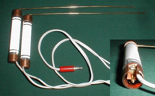


Best wishes,
J_P
Reply With Quote
  #36  
Old 02-09-2012, 05:35 PM
J_Player's Avatar
J_Player J_Player is offline
Guru
 
Join Date: Feb 2006
Location: California
Posts: 4,382
Default

Quote:
Originally Posted by michael View Post
Hi J_P
yes, that's right.
it has no output range, just 6 preset output frequency + those 7 funny user-set options.
I don't remember exactly LRL2000D wave voltage. just know Notsi LRL2000D amp is TDA7294. I think have put the info somewhere in this forum.
After that my friend made one radio frequency generator with very vast frequency range (from 1Hz to 500KHz) I remember its' amp was STK435. my test result for this one was the same as Notsi LRL.

I am guessing the frequency meter you used is a portable battery operated frequency counter that has an aerial antenna and two test probes with alligator clips, that do not have a shield.
From what you say, you got no signal except when you tried at a way you call ground mode.
yes, that's right.

I have difficulty to understand how you connected the two alligator clip leads.
From what I read it sounds like you dropped both alligator clip wires into a vase that you buried in the ground.
No, As I wrote, I planted two iron rod in ground and plugged each alligator to each one.

But I believe you made some detection at the distance you say.
Yes, it could be detectable in all directions/paths

Maybe if we learn the voltage and frequency at the MFD probes and the distance they were set apart, and exactly where each of the two frequency counter probes were connected to, we would have some idea how to make a similar test.
I checked for each frequency, all were detectable up to 2 meters.
MFD probes distance was ordinary; 30-40 Cm. had no difference in result.
FR-counter probes distance also were close; 20, 30 or 40 Cm.

One question:
Did your Bulgarian locator work to locate any treasures?

No, never and ever.

Best Wishes.
Hi Michael,
Now it begins to make sense that you measured a signal in the ground much farther than I did.
The TDA7294 in your Bulgarian locator is a 100 Watt amplifier running at 24 volts.
Interestingly enough, this is an audio amplifier intended for high power home stereo sound systems.
And the specs are quite good for an integrated amplifier.
When putting out 50 watts of power, the maximum harmonic distortion is 0.1% over a range from 20Hz to 20 KHz.
This means if you put a very clean sine wave into this IC, it will deliver a very clean sine wave out, except at a much higher power level.
The best part is you don't need to build huge circuit board full of transistors to attain this power.
It is all contained inside the single IC. You simply add a few resistors and capacitors around the TDA7294.
But if you connect the TDA7294 in a way that allows it to put out a full 100 watts of power, then you will need a good size heat sink to dissipate the heat that comes from the IC.

I don't know how the power was transferred from the TDA7294 to the ground in your in your LRL5000D, but I am guessing they connected directly from the output terminals to ground probes.
If this is the case, your ground probes reached nearly 24v peaks, which partly explains how you could find your MFD signal at a greater distance.
Most other commercial MFD oscillators run at 5v or 9v.
But another very big thing that can change the distance you can measure this frequency in the ground depends on the ground conductivity and the distance your ground probes are separated from each other.

In any case, the extra distance you could measure the oscillator signal did not seem to have any effect that helped to find buried treasures.
But this IC could be useful for people who believe that more power is better.
I imagine you could find the ground signal is detectable at even greater distances if you were to match the output impedance to the ground.
This would be easy to do with a transformer.
But I would not expect to see any change in your results if you were to go to the trouble to try it.


Best wishes,
J_P
Reply With Quote
  #37  
Old 02-10-2012, 07:44 AM
Dedevil Dedevil is offline
Banned
 
Join Date: Oct 2011
Location: Hell
Posts: 262
Default holding his own hand

I believe he is just holding his own hand and trying to lead us all down his golden path.

It's an audio amplifier and nothing to do with l rods unless you connect the output to a speaker and give the ground a sonic blast.
Don't Laugh! This system is actually used for offshore geophysical detection. But the blasts are much louder.
rgds

Last edited by Dedevil; 02-10-2012 at 07:50 AM. Reason: after thought
Reply With Quote
  #38  
Old 02-10-2012, 09:00 AM
J_Player's Avatar
J_Player J_Player is offline
Guru
 
Join Date: Feb 2006
Location: California
Posts: 4,382
Default

It turns out this TDA7294 amplifier is even more interesting than I thought.
Aside from being a very low distortion high power amplifier, it runs on a dual power supply that the signal generator IC can share with it.
This means you can use the two 12v batteries like Michael has in his Bulgarian LRL to run both the TDA7294 power amp and the signal generator.
The output from this amp will be higher because of it's 24 volt supply instead of the 12v that the signal generator is using above.
But this is not a problem, the 8038 signal generator is good for up to 30 volts each side of the supply.
So we can plug it into the same supply and send the signal to the TDA7294 all on the same board if we want.
This seems quite convenient for MFD builders.

This amplifier is intended to drive typical speakers from 4-8 ohms. Since the ground usually has much higher impedance, We cannot expect to put the full 100 watts of power into the ground.
But since it can handle up to 100 watts, it seems a good candidate for a step-up transformer to increase the voltage at the probes to get more power into the ground.
Of course, power transistors could do this too. The main difference is this IC is able to maintain a very clean signal without distorting it at power levels, and it is on a single IC.
When we start sending more power out, we can expect the amplifier to heat up, so we need a heat sink that will carry the heat away.
The image below shows a typical heat sink used on an audio amplifier.
But this could be made smaller, especially if you include a fan to circulate air through the fins, similar to how computer fans work.

Because this IC matches up so well to the 8038 signal generator, I show some concepts of how you could hook it up below.
This is not a circuit I tested, but I think it may work if I didn't get any mistakes in the connections.

In the circuit you can see I changed the two capacitors that set the frequency for the 8038 to a bank of 6 capacitors with a rotary switch to select which frequency you want.
You can fill in any capacitor values for your favorite frequencies.
There is also an option to make adjustments to the frequency at pin 4 on the 8038, or you can leave it in the original design.
You can also see where the transformer goes.
You can choose the transformer type depending on the soil conditions.
I think you will have a wide range of soil impedance depending on ground mineralization and how wet the soil is.
For this reason, I doubt any one transformer would be suitable for all soil.
But at least you have some control at the power knob.
Another option would be an adjustable auto-transformer that you can change to suit the soil.
But don't forget the batteries.
When you put out more power, you need bigger batteries.

Keep in mind that Michael's Bulgarian MFD locator uses this same amplifier, but he was able to detect nothing ever, even though he could measure the signal in the ground up to 2 meters distance.
And that is exactly what I think you will detect with this MFD detector... Nothing.
If you think I am wrong and this circuit really can locate treasure, prove me wrong.


Best wishes, J_P
Attached Images
 
Reply With Quote
  #39  
Old 02-11-2012, 12:54 PM
Dedevil Dedevil is offline
Banned
 
Join Date: Oct 2011
Location: Hell
Posts: 262
Default Have you thought of?

Quote:
Originally Posted by J_Player View Post
It turns out this TDA7294 amplifier is even more interesting than I thought.
Aside from being a very low distortion high power amplifier, it runs on a dual power supply that the signal generator IC can share with it.
This means you can use the two 12v batteries like Michael has in his Bulgarian LRL to run both the TDA7294 power amp and the signal generator.
The output from this amp will be higher because of it's 24 volt supply instead of the 12v that the signal generator is using above.
But this is not a problem, the 8038 signal generator is good for up to 30 volts each side of the supply.
So we can plug it into the same supply and send the signal to the TDA7294 all on the same board if we want.
This seems quite convenient for MFD builders.

This amplifier is intended to drive typical speakers from 4-8 ohms. Since the ground usually has much higher impedance, We cannot expect to put the full 100 watts of power into the ground.
But since it can handle up to 100 watts, it seems a good candidate for a step-up transformer to increase the voltage at the probes to get more power into the ground.
Of course, power transistors could do this too. The main difference is this IC is able to maintain a very clean signal without distorting it at power levels, and it is on a single IC.
When we start sending more power out, we can expect the amplifier to heat up, so we need a heat sink that will carry the heat away.
The image below shows a typical heat sink used on an audio amplifier.
But this could be made smaller, especially if you include a fan to circulate air through the fins, similar to how computer fans work.

Because this IC matches up so well to the 8038 signal generator, I show some concepts of how you could hook it up below.
This is not a circuit I tested, but I think it may work if I didn't get any mistakes in the connections.

In the circuit you can see I changed the two capacitors that set the frequency for the 8038 to a bank of 6 capacitors with a rotary switch to select which frequency you want.
You can fill in any capacitor values for your favorite frequencies.
There is also an option to make adjustments to the frequency at pin 4 on the 8038, or you can leave it in the original design.
You can also see where the transformer goes.
You can choose the transformer type depending on the soil conditions.
I think you will have a wide range of soil impedance depending on ground mineralization and how wet the soil is.
For this reason, I doubt any one transformer would be suitable for all soil.
But at least you have some control at the power knob.
Another option would be an adjustable auto-transformer that you can change to suit the soil.
But don't forget the batteries.
When you put out more power, you need bigger batteries.

Keep in mind that Michael's Bulgarian MFD locator uses this same amplifier, but he was able to detect nothing ever, even though he could measure the signal in the ground up to 2 meters distance.
And that is exactly what I think you will detect with this MFD detector... Nothing.
If you think I am wrong and this circuit really can locate treasure, prove me wrong.


Best wishes, J_P

Get off that space flight from NASNA and back to reallity?

We are searching for an LRL THAT WORKS
Reply With Quote
  #40  
Old 02-11-2012, 05:50 PM
J_Player's Avatar
J_Player J_Player is offline
Guru
 
Join Date: Feb 2006
Location: California
Posts: 4,382
Default

Quote:
Originally Posted by Dedevil View Post
Get off that space flight from NASNA and back to reallity?

We are searching for an LRL THAT WORKS
Do you have an MFD schematic that works?
Post the schematic here.


Best wishes,
J_P
Reply With Quote
  #41  
Old 02-11-2012, 06:23 PM
Geo's Avatar
Geo Geo is offline
Guru
 
Join Date: Mar 2005
Location: Greece
Posts: 3,914
Default

Quote:
Originally Posted by J_Player View Post
Do you have an MFD schematic that works?
Post the schematic here.


Best wishes,
J_P

Most MFD works if the user knows how to keep the rods. Do not you wait from first time to keep the Lrods and to go directly to the buried objects . As all the things.. it need hard work

Regards
__________________
Geo
Reply With Quote
  #42  
Old 02-11-2012, 07:53 PM
J_Player's Avatar
J_Player J_Player is offline
Guru
 
Join Date: Feb 2006
Location: California
Posts: 4,382
Default

Quote:
Originally Posted by Geo View Post
Most MFD works if the user knows how to keep the rods. Do not you wait from first time to keep the Lrods and to go directly to the buried objects . As all the things.. it need hard work

Regards
Hi Geo,
The technique you specify for using MFD was already posted above here: http://www.longrangelocators.com/for...1&postcount=10

This thread is where ma330 asked for an mfd project and a schematic that works.
Do you have a project and schematic to post here that can help him?
Quote:
Originally Posted by ma330
I need information about a mfd project.And I need a schematic for mfd.Can anyone help me?

Best wishes,
J_P
Reply With Quote
  #43  
Old 02-11-2012, 08:38 PM
Geo's Avatar
Geo Geo is offline
Guru
 
Join Date: Mar 2005
Location: Greece
Posts: 3,914
Default

Quote:
Originally Posted by J_Player View Post
Hi Geo,
The technique you specify for using MFD was already posted above here: http://www.longrangelocators.com/for...1&postcount=10

This thread is where ma330 asked for an mfd project and a schematic that works.
Do you have a project and schematic to post here that can help him?


Best wishes,
J_P
Hi J_P.
It is not so simple!!!. Don't think that if you will keep 2 Lrods at your hand then you will find any buried. It needs many experiment.
As for schematic... i attached one LRL with generator and it works.

Regards
__________________
Geo
Reply With Quote
  #44  
Old 02-11-2012, 08:50 PM
J_Player's Avatar
J_Player J_Player is offline
Guru
 
Join Date: Feb 2006
Location: California
Posts: 4,382
Default

Quote:
Originally Posted by Geo View Post
Hi J_P.
It is not so simple!!!. Don't think that if you will keep 2 Lrods at your hand then you will find any buried. It needs many experiment.
As for schematic... i attached one LRL with generator and it works.

Regards
Hi Geo,
This is excellent information.
Can you post a list of the experiments that are necessary to find buried treasure for ma330?
When he finishes performing the experiments that you show, then he will find treasure the same as you find treasure.

Also, I do not see your attachment for LRL with generator schematic that works.
Can you post that too?


Best wishes,
J_P
Reply With Quote
  #45  
Old 02-12-2012, 10:21 AM
Dedevil Dedevil is offline
Banned
 
Join Date: Oct 2011
Location: Hell
Posts: 262
Default Thanks Geo

Excellent ciruit diagram of your LRL. Is this your own design? Which program did you use to draw the diagram?

rgds
Reply With Quote
  #46  
Old 02-12-2012, 10:45 AM
ma330 ma330 is offline
Senior Member
 
Join Date: Mar 2006
Posts: 112
Default

hi jp
You can design for my post number 38 with IC xr2206 Instead of 8038?
with respect
Reply With Quote
  #47  
Old 02-12-2012, 11:43 AM
Dedevil Dedevil is offline
Banned
 
Join Date: Oct 2011
Location: Hell
Posts: 262
Default Thanks Geo

Quote:
Originally Posted by Dedevil View Post
Excellent ciruit diagram of your LRL. Is this your own design? Which program did you use to draw the diagram?

rgds
Just a question? In your schematic after the Ls888tx1 what is the purpose of the output of the R/C circuit.

rgds
Reply With Quote
  #48  
Old 02-12-2012, 12:30 PM
ma330 ma330 is offline
Senior Member
 
Join Date: Mar 2006
Posts: 112
Default

Quote:
Originally Posted by Geo View Post
Hi J_P.
It is not so simple!!!. Don't think that if you will keep 2 Lrods at your hand then you will find any buried. It needs many experiment.
As for schematic... i attached one LRL with generator and it works.

Regards
HI GEO
I can not see your files.
Please put your files in RAR format
TANK YOU
Reply With Quote
  #49  
Old 02-12-2012, 01:38 PM
Dedevil Dedevil is offline
Banned
 
Join Date: Oct 2011
Location: Hell
Posts: 262
Default Questions, questions?

Hi Geo

I still do not understands from your schematic posted above as you say R/C if for feedback from pin2?
Is this voltage or magnetic type?

This is a very different type of LRL

rgds
Reply With Quote
  #50  
Old 02-12-2012, 03:57 PM
Geo's Avatar
Geo Geo is offline
Guru
 
Join Date: Mar 2005
Location: Greece
Posts: 3,914
Default

Quote:
Originally Posted by Dedevil View Post
Just a question? In your schematic after the Ls888tx1 what is the purpose of the output of the R/C circuit.

rgds
Hi.
I don't remember at who post you refered..

Regards
__________________
Geo
Reply With Quote
Reply


Posting Rules
You may not post new threads
You may not post replies
You may not post attachments
You may not edit your posts

BB code is On
Smilies are On
[IMG] code is On
HTML code is Off

Forum Jump


All times are GMT. The time now is 12:28 AM.


Powered by vBulletin® Version 3.8.11
Copyright ©2000 - 2024, vBulletin Solutions Inc.