
|
|
#381
 03-11-2021, 05:24 PM
|
|||
|
|||
|
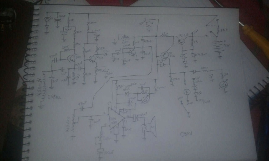
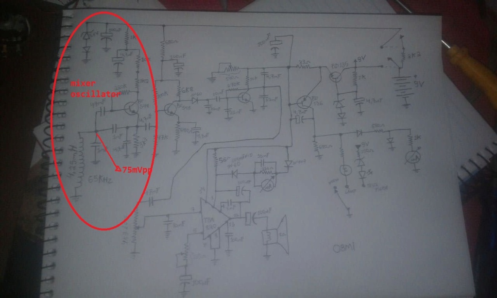
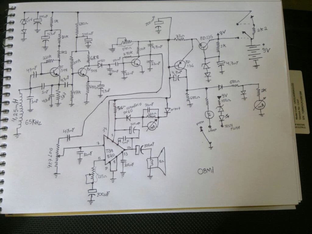
Good afternoon friend. Very interesting this circuit of the detector of two boxes of the miner, the 08Mi. This circuit is from the receiver, another curiosity: the input coil together with the transistor and surrounding components is also part of a colpitts oscillator, of low amplitude, the signal generated is approximately 65khz, with an amplitude around 70mvpp . The transmitter signal has a potentiometer where it is possible to adjust the transmission frequency around 60 to 70khz, by adjusting the same frequency to the receiver, which is 65khz, the detector is silent, because the beat of the two frequencies is zero, normally used The device so that you can hear a low frequency sound in the speaker, means that the transmitter must be adjusted around 300 hz more or less than that of the receiver. boxes also acts as a BFO, being able to detect even small things. The first transistor, in addition to functioning as an oscillator, also functions as a signal mixer, where the transmitter signal is induced in the receiver's oscillating coil, the mixed signal is removed from the emitter and amplified by the next transistor, and through the germanium diode the signal is detected, and through the capacitor the high frequencies are filtered, leaving only the audio signal referring to the difference in the signal of the two transmitters. This signal is amplified again and filtered by capacitors and this audio signal goes to the sensitivity setting which is the volume potentiometer of the tba820 amplifier. Another interesting arrangement is in the circuit that provides visual indication through the VUS, a regulated source is made by the transistor bd135, where we will have a constant voltage in its emitter, the tba820 amplifier is fed in series with a 33R resistor, this is a shunt resistor, where in parallel with it is the bd136, when the signal strength is strong in the speaker a current circulates through this 33R resistor which causes a voltage drop in it, which in this case will be something in around 0.6v for the bd136 to start conducting and present a voltage in its collector, a voltage that will produce the displacement of the pointers of the vu, or turn on the night search lamp if it has been selected by the operator, this is the VU of small signals.

|
|
#382
03-11-2021, 05:28 PM
|
|||
|
|||
|
a regulated source is made by the transistor bd135, where we will have a constant voltage in its emitter, the tba820 amplifier is fed in series with a 33R resistor, this is a shunt resistor, where in parallel with it is the bd136, when the signal strength is strong in the speaker a current circulates through this 33R resistor which causes a voltage drop in it, which in this case will be something in around 0.6v for the bd136 to start conducting and present a voltage in its collector, a voltage that will produce the displacement of the pointers of the vu, or turn on the night search lamp if it has been selected by the operator, this is the VU of small signals.
|
|
#384
03-11-2021, 05:44 PM
|
|||
|
|||
|
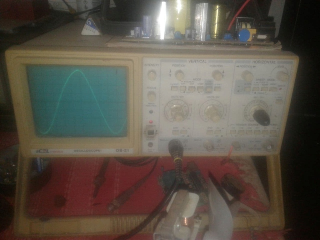
Exactly Geo, I believe that you can improve its operation in order to work better as a long-distance detector, reducing the power of the transmitter and further lowering the amplitude of the oscillating coil, in order to detect signals of much smaller amplitudes, now it remains to know how to design an oscillator that generates a sine wave of a lower amplitude than that of the miner, which in this case was 75mvpp, I think that if we could design one with an amplitude of only 5mvpp, and increasing the gain of the pre amplifier circuit in order to be able to detect this signal later, we would have a very efficient long-distance detector, remembering that the power of the transmitter at the back would have to be reduced so that the receiver and oscillator coil would be only about 5mv as well.
|
|
#386
03-12-2021, 06:28 AM
|
||||
|
||||
|
Quote:
At wich point did you measud it???
__________________
Geo
|
|
#387
03-12-2021, 06:31 AM
|
||||
|
||||
|
Quote:
Before years two friends said me that they measured it and was a small drift. Maybe at 100Khz 50...100Hz, i don't remember exactly 
__________________
Geo
|
|
#395
03-12-2021, 08:22 PM
|
|||
|
|||
|
Quote:
|
|
#397
03-13-2021, 05:52 AM
|
||||
|
||||
|
Quote:
The signal of buried metals or the phenomenon modulates the signal of oscilator and the diode demodulate it, so the signal of oscillator is not problem. I have see similar techniques where the signal at base is 150.. 200 mv so the 75mv of this oscillator is very good. You must adjust the transmiter right so to works as stimulator coil... Regards
__________________
Geo
|
|
#399
04-25-2021, 11:44 AM
|
|||
|
|||
|
yes
|
 |
|
|


 . please upload TX circuit too
 Linear Mode

