
|
|
#2952
 01-18-2023, 10:30 AM
|
||||
|
||||
|
Quote:
.......link not downloadable 
|
|
#2956
01-18-2023, 07:06 PM
|
||||
|
||||
|
Quote:
i did as you said ...but it not downloaded.anyway thanks for your guide .
|
|
#2958
01-21-2023, 02:28 PM
|
|||
|
|||
|
Hello, if anyone is interested, this is my version of the "Franco LRL" still under construction. I am Italian, like Mr. Franco and I am a designer. It may seem strange, but I always try to create and possibly reuse objects that were previously intended for another use. I study the feasibility and then adapt everything. In this case I used the plastic cover of a bottle of Italian men's perfume. The handle, which will contain the 2 batteries, is instead a bottle of shampoo. Don't pay attention to the graphics because they are my decorative writings.
|
|
#2959
01-21-2023, 03:19 PM
|
|||
|
|||
|
In my laboratory I keep all the plastic containers that I might need in the future. However, what matters is the substance, not the appearance.
|
|
#2960
01-21-2023, 11:42 PM
|
|||
|
|||
|
Quote:
Of course Mr. Franco, you must forgive me because the creative and aesthetic side is in my nature and I always try to put a little of it into everything I do. I try to recycle when I can. However it's right that, especially in an electronic assembly, the essential thing is the correct functioning and for this I will surely need your help since I'm not an expert at all and who better than you can give advice, since the lrl is your project? For now I'm going ahead with the assembly, later, maybe I'll ask you to guide me in the calibration. Thank you
|
|
#2961
01-28-2023, 03:06 PM
|
||||
|
||||
|
hello for all , my name is sweker ,and I am interested in lrl that made by franco , I have already constructed it it work for near distance , actually I am facing problems with antenna setup, will left some picture that may help , I need your opinion Mr franco[/FONT]
|
|
#2962
01-28-2023, 03:37 PM
|
|||
|
|||
|
Since my lrl is a passive receiver there is almost certainly not enough amplification in the sensor stage. In fact, I recommend adjusting the amplification just below the self-oscillation threshold and for this you need transistors with gain >500. The pcb is important, it must be double-sided or with shielding on the lower part, this is to prevent self-oscillation before having sufficient gain. If this is not enough you can increase the gain in the display stage.
|
|
#2964
01-29-2023, 10:14 AM
|
|||
|
|||
|
I'm sorry but I'm not able to give an opinion, however it has a professional look; I used a pcb only for the sensor stage to minimize the possibility of self-oscillations and I can't tell if a single pcb for the whole lrl is valid. The only possibility is to use a pcb tested by others and certainly working.
|
|
#2966
02-02-2023, 03:21 PM
|
|||
|
|||
|
Quote:
|
|
#2967
02-14-2023, 12:32 AM
|
|||
|
|||
|
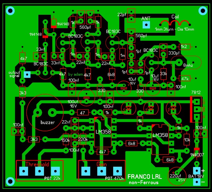
Hi Omar, I realize only now that in your pcb C6 and C8 (electrolytic capacitors) are marked with a value of 10 uF, while on the diagram, Mr. Franco puts them at 100 uF, I wanted to confirm if this is a writing error. Thank you
|
|
#2968
02-19-2023, 11:45 AM
|
|||
|
|||
|
Plesae, I know it may seem like a trivial question, but can someone tell me where the out voltage should be measured, which must be around 5 Volts, point n. 1 or 2?.
I would not have made a mistake so far to measure it on the TR5 emitter.
|
|
#2969
02-19-2023, 01:20 PM
|
|||
|
|||
|
Unfortunately this forum has lost interest, a pity because there will always be someone who will arrive late... I always measured at point 1, but if instead the voltage is to be measured at point 2, I must surely change something, such as the network of capacitors from 1pF.
|
|
#2970
02-21-2023, 08:45 AM
|
||||
|
||||
|
Quote:
|
|
#2971
02-21-2023, 10:19 AM
|
|||
|
|||
|
In my opinion it is not possible in fact even by connecting an oscilloscope the signal is interrupted.
|
|
#2972
03-27-2023, 03:27 PM
|
|||
|
|||
|
[QUOTE=Inna;162126]Hi Omar, I realize only now that in your pcb C6 and C8 (electrolytic capacitors) are marked with a value of 10 uF, while on the diagram, Mr. Franco puts them at 100 uF, I wanted to confirm if this is a writing error. Thank you
Hi my friend these capacitors are to smooth the current. Put what you see fit. I ask you to view this blog to understand more about some things, as it is similar to the Franco device. http://techlib.com/electronics/allband.htm
|
|
#2973
03-27-2023, 04:19 PM
|
|||
|
|||
|
The circuit is interesting, but I have some doubts about the values of 10M and 100k, they seem too high for bipolar transistors.
|
|
#2975
03-30-2023, 10:15 AM
|
|||
|
|||
|
The antenna seems too short, I recommend in the 30-40cm range, increasing the length of the antenna increases the sensitivity and vice versa.
|
 |
|
|


 Linear Mode

