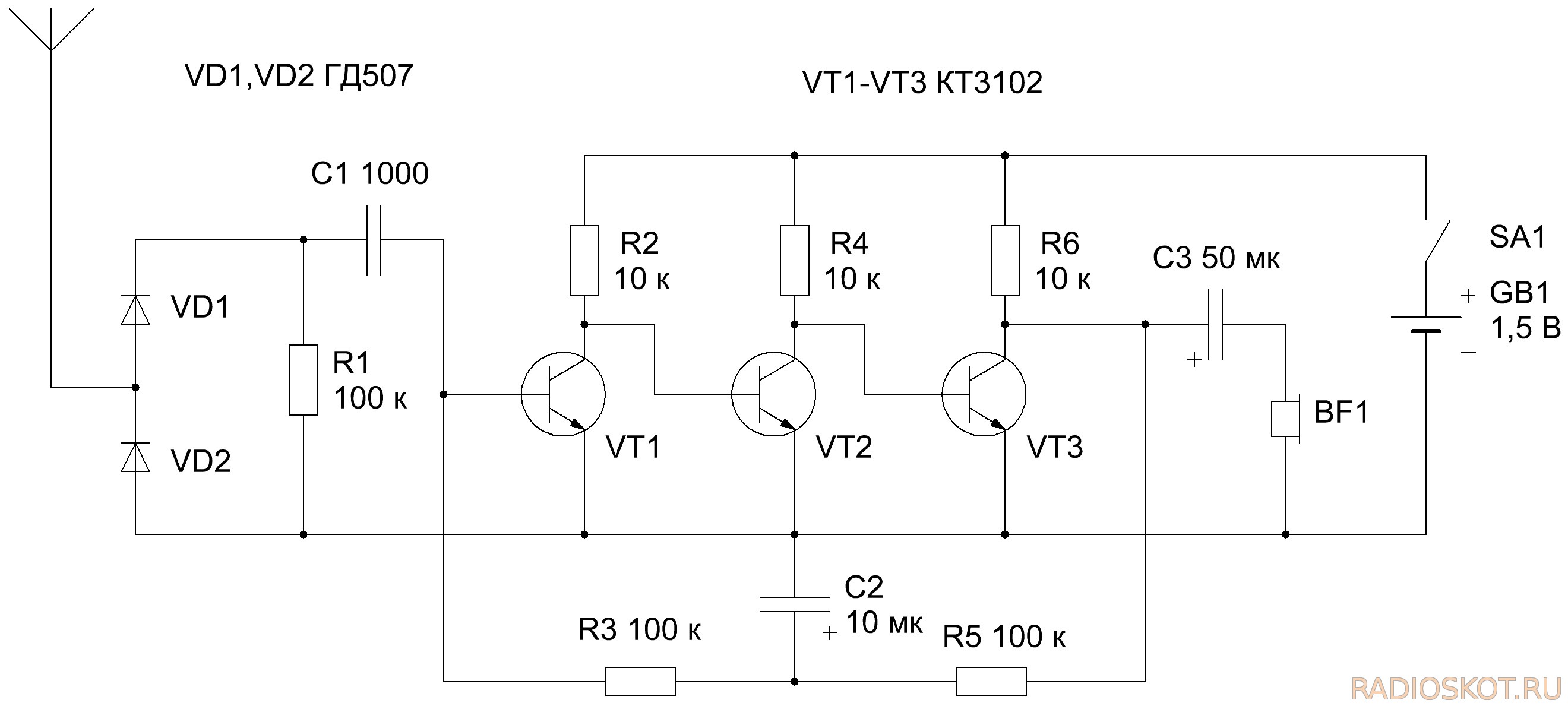
This detector of electromagnetic waves is described in the journal "Radiomir» №4 in 2011 in an article by Professor "Simple broadband detector signals" (p. 3

. Here is completely redraw the diagram below:


There are several drawings are reduced, you can
download an archive of the source drawings. Circuitry is straight receiver. The signal from the antenna is detected by the diodes VD1 and VD2, and then enters the amplifier input transistors formed on VT1 - VT3. The device is deprived of, any means of setting a specific frequency, so that the range of audible sound is limited only by the bandwidth of the amplifier and headphone headphone capabilities. By the output of the amplifier connected conventional low-resistance headphones impedance of 32 ohms. In this structure, it is necessary to connect the headphone transducers sequentially so that the total resistance of the phone was about 60 ohms.

Diodes VD1 and VD2 - germanium, the author applied GD507, but probably you can use any low-power high-frequency germanium diodes, such as D311, D9, D18, D20. Transistors VT1 - VT3 type KT3102. In the primary source indicated that it is possible to use imported BC547. Telescopic antenna, long, about 30 cm, but you can do the hard segment of wire of the same length. Power is supplied by a single element 1.5 V AA batteries. The device is assembled psevdopechatnym installation.

The detector allows you to dive into the world of invisible low-frequency electromagnetic signals. So at a distance of about 1 m from the cable clearly audible transmission wire broadcasting network, the characteristic low rumble can be found wire household power, very characteristic sound Switching Power Supplies. Almost device can be used to detect hidden wiring , interference sources . Thank you for your attention. The author Lekomtsev D.


 . Here is completely redraw the diagram below:


