
|
|
|
|
#1
 02-07-2019, 02:35 PM
|
|||
|
|||
|
Figured it was easier to start a new thread but it's the same problem--coil goes to ground and I want to isolate it from the other circuits. The battery (voltage regulator), the signal generator all go to ground and I do not want the coil signal connected to these.
It just seems like this is what i might need but have no electronics knowledge here. I've watched some videos on this but that's as far as i got. I would appreciate if if anyone could steer me to a place I could learn more about this in order to design something. Thanks. Well, at least I think that is what I need. Not really sure about anything here. This article talks about the TLE2426 noise reduction. https://tangentsoft.net/elec/vgrounds.html Pretty sure I am over my knowledge ability here so don't anybody spend too much time on this or you will get frustrated with me for sure.  This is not your regular coil circuit and I think I need to get some professional help. I mean WITH THE CIRCUIT!!!

|
|
#2
02-07-2019, 04:34 PM
|
||||
|
||||
|
The schematics that there are at linked page are to supply with symetrical voltage the op. amplifiers from a simple supply.
BUT i can't understand what you want to build so to say if schematics are ok or not  . .
__________________
Geo
|
|
#3
02-07-2019, 04:47 PM
|
||||
|
||||
|
All explanation you can find in link you give to us here.
Apart from dual power supply all other solution are based on resistor divider solution. This one (taken from your link): 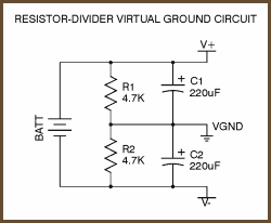 So you need to start with voltage divider theory to go further with understands. Geo proposed you, couple days ago, to post your idea/schematic or at least part of those schematic to make discuss and help possible. This is still valid. It's not uncommon to see multiple grounds in a circuit and it's normal for these to be joined together at some point: either directly, or par example with a zero ohm resistor. The reason you have multiple grounds is to control the return path for various currents. Digital circuits for example may contain fast edges in signals and so have the potential of introducing significant noise. Separating the digital from analog ground allows you to keep the analog signals clean of any noise from the digital switching. The digital ground will contain noise but this matters less as you are only interested in logic high or low; the exact voltage is less important. The two grounds will be "starred" together at some point perhaps directly at the capacitor lead of the power supply. Those ground in circuit, that are not directly linked to (-) negative pole of power supply is treated as virtual ground.
__________________
Global capital is ruining your life? You have right to self-defence!
|
|
#4
02-07-2019, 06:07 PM
|
|||
|
|||
|
Thanks for your help. Yes, this is not a typical coil circuit. I don't wish to describe it. But if you know how a pulse induction coil spikes--this is what i need to isolate from everything else. i will continue to study the virtual ground to try to isolate the voltage spike off the coil to ground.
|
|
#5
02-08-2019, 04:36 AM
|
|||
|
|||
|
All this talk about flyback voltage I don't see any reason why I can't try a damping resistor to see if it will quiet things down some. Yeah, I'm desperate and grasping at straw, but never know until I try. Recall my motto "Cheap overkill". Finding the right value is the big obstacle but I can do it like Edison, just keep trying 10,000 times.
I have the formula in the ITMD book but don't have all the numbers to calculate it with, so maybe I'll get out my dowsing rod and put a bunch of resistors on the table and see which one I get a lock on. Just a joke.
|
|
#6
02-08-2019, 07:25 AM
|
||||
|
||||
|
Quote:
wild oscillation (if R-damping is to high). To find proper value of damping resistor it is better to use potentiometer and replace it at the end with single resistor of exact value: 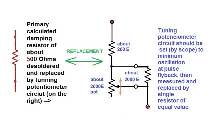
__________________
Global capital is ruining your life? You have right to self-defence!
|
|
#7
02-08-2019, 02:03 PM
|
|||
|
|||
|
Thanks for the info. Yes, part of the issue I see now is I am not using one set frequency. So i might end up with a rotary switch with several different resistors. I'll give it a shot today and see if anything improves.
|
|
#8
02-16-2019, 02:17 PM
|
||||
|
||||
|
Quote:
Hello my friend This circuit can help you Used on many devices
__________________
No matter how the speed of light is high , Darkness is one step ahead .
|
|
#9
02-16-2019, 02:36 PM
|
|||
|
|||
|
Thanks Reza Vir, after viewing your schematic I just remembered the L7805 can use capacitors.My brain is not so sharp after all my melt-downs, personal trauma, etc. and more to come. I have nothing left to lose at this point.
|
|
#10
02-16-2019, 03:50 PM
|
|||
|
|||
|
I found the caps I need so will get it together later today and see what happens. I feel like I am mentally challenged. Okay, I am.
Thanks for your help.
|
|
#11
02-16-2019, 06:26 PM
|
|||
|
|||
|
Didn't cost me anything except my time. thanks for trying to help me. I'm kinda beyond help.
I just installed the caps as per the photo I posted. I couldn't notice any difference. I thought about adding the 1N4007 as per your schematic. But if I go that route, I'll need a higher voltage battery, a different battery charger, balancer board. Just don't feel like spending the money on this--money i don't have. Besides, this circuit is not the same. i just want to quit working on this Contraption. Maybe, okay, probably after I get skunked a few times i will get in the panic mode.
|
|
#12
02-16-2019, 11:55 PM
|
|||
|
|||
|
i even exchanged the 0.33uF for the 10uF electrolytic and no change. I did notice it ran quite a bit warmer with the caps so I removed them and it cooled down. This is with a heat sink on it.
So back to where i was. I tried and failed again. It's okay, I'm just leaving it like this for now. I can live with it until I find out what happens in the field this Spring. So no gasoline or suicide just yet.
|
 |
|
|


 Hybrid Mode
