All explanation you can find in link you give to us here.
Apart from dual power supply all other solution are based on resistor divider solution.
This one (taken from your link):
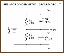
So you need to start with voltage divider theory to go further with understands.
Geo proposed you, couple days ago, to post your idea/schematic or at least part
of those schematic to make discuss and help possible. This is still valid.
It's not uncommon to see multiple grounds in a circuit and it's normal for these to
be joined together at some point: either directly, or par example with a zero ohm resistor.
The reason you have multiple grounds is to control the return path for various currents.
Digital circuits for example may contain fast edges in signals and so have the potential
of introducing significant noise.
Separating the digital from analog ground allows you to keep the analog signals clean
of any noise from the digital switching.
The digital ground will contain noise but this matters less as you are only interested in logic
high or low; the exact voltage is less important.
The two grounds will be "starred" together at some point perhaps directly at the capacitor
lead of the power supply.
Those ground in circuit, that are not directly linked to (-) negative pole of power supply is
treated as virtual ground.